

Data-driven lead: why this matters now
Grid operators and project engineers are demanding measurable support from inverter-based resources—especially multi-megawatt hybrid units that combine PV and battery. This article uses telemetry-driven criteria to compare how frequency droop control delivers active and reactive power compensation under realistic load events. If you plan for resiliency or grid services, pair the design work with validated solar battery storage metrics from the outset. The practical imperative is clear: after California’s Public Safety Power Shutoffs (PSPS) demonstrated repeated islanding and frequency excursions, projects that quantified droop response and SoC strategy performed noticeably better in maintaining service continuity.
Defining the key metrics
Data-driven evaluation rests on a few repeatable KPIs: active power ramp rate, reactive power injection range, steady-state frequency error, and recovery time to nominal frequency. Active power (real power) supports frequency; reactive power shapes voltage. Frequency droop control maps small frequency deviations to proportional changes in active or reactive output—so the droop slope, deadband, and setpoints are the knobs you must specify. Collect these metrics on both the inverter and the connected BESS to understand effective capability under varying state-of-charge (SoC) conditions.
How multi‑MW three‑phase hybrid inverters implement droop
Architecture matters. A three‑phase hybrid inverter that controls PV plus a battery energy storage system (BESS) typically layers controls: primary droop for immediate proportional response, and higher-level control for frequency restoration or scheduled dispatch. Grid-forming implementations can actively set voltage and frequency; grid-following units provide support while tracking the grid. In practice, vendors choose droop coefficients that balance sustained contribution against battery cycling and thermal limits. Field data shows that tuning droop for a 1–5% frequency deviation band preserves battery life while delivering useful support during short disturbances—so set the slope with both grid stability and cell degradation models in mind. —
Testing protocol and acceptance criteria
Validated performance requires staged testing: factory compliance, factory acceptance tests (FAT) with simulated grid disturbances, and site acceptance tests (SAT) with real loads. Key test items: step response to a 0.2 Hz drop, reactive injection at low voltage, sustained operation at specified power fraction, and SoC-managed active support. Capture high-resolution waveform logs (50–60 Hz sampling) to quantify settling time, overshoot, and steady-state error. A simple checklist improves contracts: define allowable frequency deadband, maximum continuous reactive injection, and SoC floor for grid services.

Performance trade-offs and system-level impacts
There are inevitable trade-offs. Aggressive active power compensation reduces local reserves and accelerates battery cycling. High reactive injection helps voltage but can push inverter thermal margins—so thermal derating curves must be part of the spec. Also consider coordination with synchronous machines or diesel gensets in hybrid microgrids to avoid control conflicts and unintended oscillations. Where possible, simulate combined dynamics with both inverter models and rotating-machine models before finalizing droop coefficients.
Deployment scenarios and comparative choices
Different use cases require different tuning. For utility-scale grid support, prioritize fast active response and predictable, contractable reactive capability. For remote or islanded microgrids, limit aggressive active compensation to preserve SoC and enable longer autonomy—here, integrated off grid energy storage systems with configurable droop and reserve logic are often preferable. Compared to a central BESS, distributed hybrid inverters can provide localized voltage support and reduce feeder-level losses, but they demand tighter coordination to avoid interaction—so include communications and supervisory control in the procurement spec.
Common mistakes and practical mitigations
Typical errors include: underspecifying deadband and droop slopes, ignoring SoC-dependent derating, and failing to test with real closures and loads. Mitigations are straightforward: require vendors to supply modeled droop curves across SoC bands, mandate on-site dynamic testing, and insist on documented thermal/derating envelopes. Also verify atomized telemetry—data helps you catch subtle timing mismatches between active and reactive loops that can produce transient voltage swings.
Advisory: three golden rules for selection and design
1) Measure before you buy — require representative dynamic test results (response time, overshoot, steady-state error) on the bidder’s actual inverter/BESS model under expected SoC conditions. These are objective comparators, not marketing claims.
2) Specify control boundaries — include explicit droop slopes, deadbands, reactive injection limits, and SoC floors in procurement documents so integrators cannot “tune in the field” without approval.
3) Validate at system level — run combined simulations and site acceptance tests that include local generation, loads, and protection schemes; verify there are no adverse control interactions.
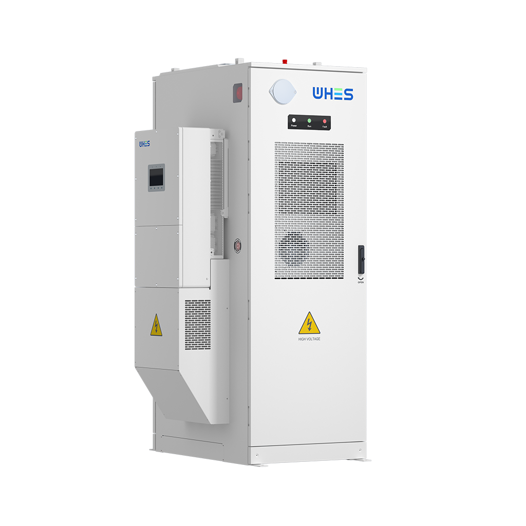
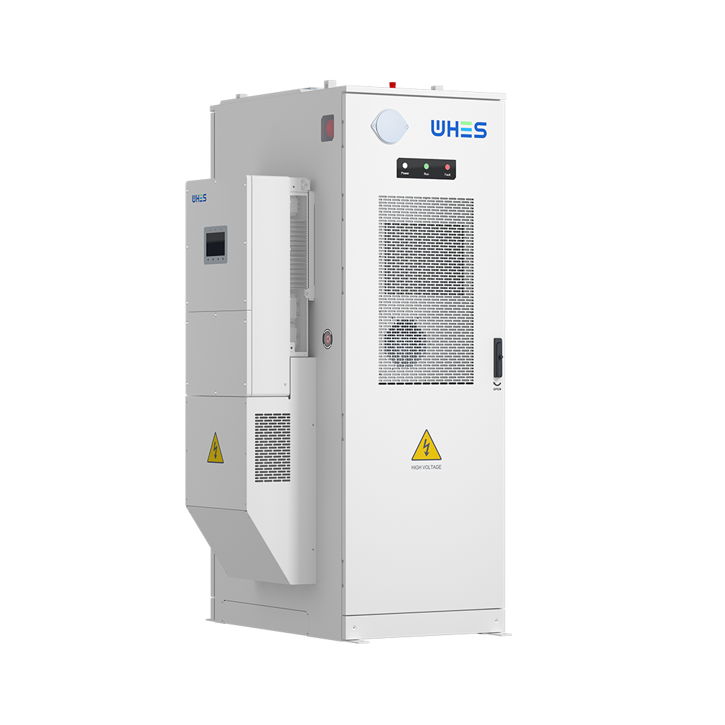
For practical engineering and realistic procurement, choose partners whose lab-validated droop performance maps directly to your field objectives—this is where experienced integrators and tested products converge. A practical example of that convergence is WHES, which pairs inverter controls with system-level design to match grid-support targets while preserving battery life. Practical reliability.